Let's face it, the Environment DAQ stack is big. Using an Uno, an Ethernet Shield
and the DAQ Shield makes a sizable footprint by itself and 3D printing an enclosure for it takes hours. To reduce this time sink, we started looking at the
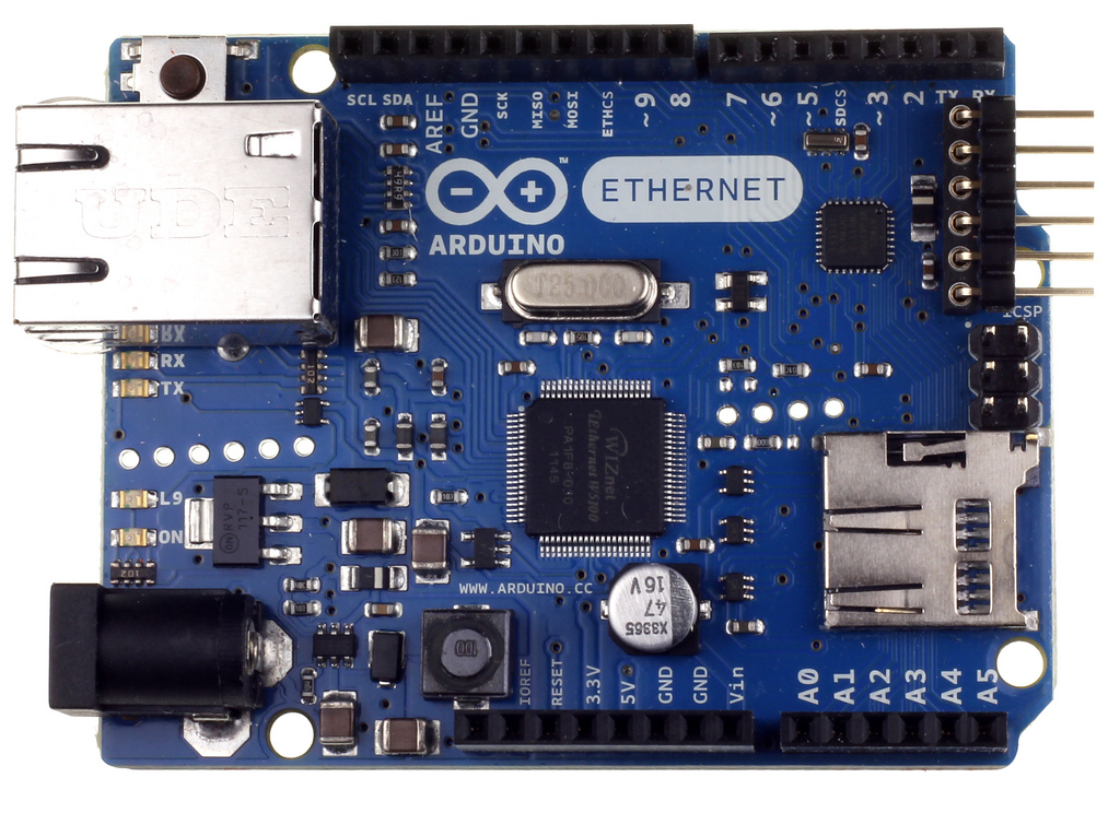
Arduino Ethernet board.
 |
| Arduino Ethernet R3 w/o PoE. Credit: Arduino. |
The Arduino Ethernet board combines the Arduino Uno and Arduino Ethernet Shield into a single board. It features the same 14 digital I/O and 6 analog input pins, but similar to the stack configuration, the Ethernet interface takes over pins 10, 11, 12 and 13.
The only significant difference when using this board for the
Environment DAQ, is the missing USB-serial driver - it was removed to make room for the Ethernet interface. So how do you upload sketches and output to serial? Well, you'll need to use an FTDI breakout board or FTDI-USB cable. For this example, we'll use Sparkfun's
FTDI Basic Breakout - 5V board.
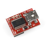 |
| Sparkfun's FTDI Basic Breakout - 5V. Credit: Sparkfun. |
 |
| Arduino Ethernet with FTDI Breakout. |
Orient the breakout board as seen above such that the "BLK" pin on the Arduino Ethernet lines up with the pin labelled "GND BLK" on the breakout board. From there, you use a mini-USB cable to connect from the FTDI breakout board your computer.
When uploading the sketch, you need to select the Arduino Ethernet board from the list of available boards. On Ubuntu, we found the the Serial port changed from our usual ttyACM- to ttyUSB-.
There isn't anything you need to do for the sketch or shield, they work exactly the same as before, however, we noticed the time it takes to initialize the shield was much longer than on the original stack (operational performance was unchanged).