Aquaponics Controllers Have Shipped

The first batch of Aquaponics Controllers have shipped!  These units are single-point, full-system controllers that are used for Aquaponics Tracker.
  • Triple-mode pump control: always on, toggle, manual
  • Depth sensor
  • Smart grow-light control 
  • Optionally use external (and therefore replaceable) relay kits
  • Water temperature
  • Industrial grade pH probe 
  • Industrial grade dissolved oxygen probe
  • Air temperature
  • Relative humidity
  • Ambient light intensity
  • Replaceable sensors
  • Uses an Arduino Mega R3 and Arduino Ethernet Shield R3
  • For use with Aquaponics Tracker or a stand-alone application
Note the application of the relays is a matter of programming rather than hardware so they are configurable as well.

Figure 1.  Early PCB layout.


Figure 2.  Aquaponics Shield.

Dry fitting components together is a no-brainer.  Below you can see the silkscreen layer printed on paper and taped to some random foam, which is excellent at holding component leads in place.  The dissolved oxygen, pH, differential pressure transducer and water temperature parts protrude from the bottom of the unit (left in the picture).

Figure 3.  Always good to dry fit.


Figure 4.  Dry fit again.


Figure 5.  Full kit.

We can't wait to get them into our 3D printed enclosures.

The Arduino Ethernet Board

Let's face it, the Environment DAQ stack is big.  Using an Uno, an Ethernet Shield and the DAQ Shield makes a sizable footprint by itself and 3D printing an enclosure for it takes hours.  To reduce this time sink, we started looking at the Arduino Ethernet board.

Arduino Ethernet R3 w/o PoE.  Credit:  Arduino.

The Arduino Ethernet board combines the Arduino Uno and Arduino Ethernet Shield into a single board.  It features the same 14 digital I/O and 6 analog input pins, but similar to the stack configuration, the Ethernet interface takes over pins 10, 11, 12 and 13.

The only significant difference when using this board for the Environment DAQ, is the missing USB-serial driver - it was removed to make room for the Ethernet interface.  So how do you upload sketches and output to serial?  Well, you'll need to use an FTDI breakout board or FTDI-USB cable.  For this example, we'll use Sparkfun's FTDI Basic Breakout - 5V board.

Sparkfun's FTDI Basic Breakout - 5V.  Credit:  Sparkfun.

Arduino Ethernet with FTDI Breakout.

Orient the breakout board as seen above such that the "BLK" pin on the Arduino Ethernet lines up with the pin labelled "GND BLK" on the breakout board.  From there, you use a mini-USB cable to connect from the FTDI breakout board your computer.  

When uploading the sketch, you need to select the Arduino Ethernet board from the list of available boards.  On Ubuntu, we found the the Serial port changed from our usual ttyACM- to ttyUSB-.

There isn't anything you need to do for the sketch or shield, they work exactly the same as before, however, we noticed the time it takes to initialize the shield was much longer than on the original stack (operational performance was unchanged).


Arduino Aquaponics: JSON

**UPDATE**
To see JSON, have a look at the Pump Controller project.

In a previous post, Online Relay Control, we demonstrated how to manually trigger a relay from a web application.  The Arduino polled App Engine on a set interval and received the status of the relay as a string; the Arduino sketch parsed the response and then analyzed the response using "if" conditionals.

While that works well for setups involving a single relay, we realize it is inherently limiting, particularly for those who want to control two relays with their Environment DAQ.  Similarly, we wanted to pair the Depth Sensor with two pumps that could be controlled independently and we needed a method of differentiating them with data from a single response.  Enter JSON.

To parse the JSON, you need aJson Library made by Marcus Nowotny.  Download, extract it and put a copy in your libraries folder.  Name the it aJSON.

The Arduino sketch below receives the following response for a GET request:

{'RELAY1': 'ON'}

and then toggles the relay.


You can see then, that returning more than one key-value pair can still be parsed from a single request.

Depth Sensor

The hardware was built directly from the Practical Arduino project, but the source code was almost completely overhauled to handle App Engine and our tank visualization, which you can see in action on the Aquaponics Tracker page.

Figure 1.  Depth sensor PCB.  The differential pressure transducer is bottom right.

Why track depth?  Actually, there are a number of reasons.  As you can see in Aquaponics Tracker, you can combine stock information with the depth to monitor the stocking density during system cycling.  You can monitor the depth for potential leaks, automatically refill the stock tank from a sump tank (due to losses from plant growth, evaporation, etc.) and when paired with pump control, you can prevent overflows and/or cycling too much water.

You can see the schematic for the depth sensor below.  The drawing is nearly identical to the Practical Arduino schematic, but we added the missing capacitor for noise reduction.

Figure 2.  Depth sensor schematic with missing capacitor.

Real-Time Clock - Part II: Grow Light Controller

In Part I of this tutorial, you learned how to set up the ChronoDot  with the Arduino and use it to track time.  Part II continues the discussion by creating a timer that can be used to control grow lights.

In a previous post we talked about the importance of light for plants and the role grow lights play in Controlled Environment Agriculture either by monitoring current light levels and providing supplemental light, or by providing all of the light for a fixed time every day.  Part II focuses on the latter, creating a timer which toggles a light on at a certain time of day, toggles it off at another and uses the ChronoDot to track the time.


Parts List
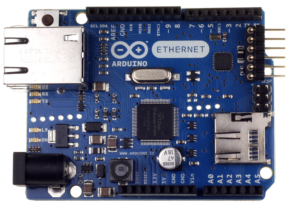
1 x Arduino Uno R3 (IDE 1.0.3)
1 x ChronoDot
1 x PowerSwitch Tail II Relay
6 x Jumper wires


Fritzing Diagram


Figure 1.  Grow Light Timer diagram.

Arduino Libraries
In addition to the libraries from Part I, you will need two new libraries for this sketch:  Time and TimeAlarms.  The Time library is used to set the Arduino's system time as well as to compare times during the initial setup.

TimeAlarms is used to create two alarms, one for the time each day the light is turned on, and a second alarm for the time of day the light is turned off.

Download both zip files, extract them and move a copy into your Arduino's libraries directory.


Arduino Sketch
This sketch takes two times, given as hour, minute and second and creates an alarm for each.  When you first launch the script, the start time and end time are compared to the current time.  If the current time is between the two times, the relay is toggled ON.

During each operational loop, the current time is retrieved from the ChronoDot, the system time is reset and the current time is displayed.